1. הקדמה
This manual provides essential information for the safe and efficient operation, installation, and maintenance of the ABB ACS150 Micro Series AC Variable Frequency Drive (VFD). The ACS150-03U-04A1-4 is a 2.0 HP, IP20 rated micro drive designed for wall mounting, operating with a 480 VAC three-phase input and providing a 480 VAC output at 4.1 Amps. It is part of the ACS150 series, known for its compact design and reliability in industrial applications.
Please read this manual thoroughly before attempting any installation, operation, or maintenance procedures to ensure proper functionality and to prevent personal injury or equipment damage.
2. זיכערקייַט אינפֿאָרמאַציע
ווארענונג: Electrical shock hazard. Only qualified personnel should perform installation, commissioning, and maintenance of this equipment. Disconnect all power before working on the drive.
- שטענדיק פֿאָלגן די לאָקאַלע און נאַציאָנאַלע עלעקטרישע קאָודן און רעגולאַציעס.
- זיכער מאַכן אַז די דרייוו און מאָטאָר זענען געהעריק גראַונדינג.
- Do not touch electrical components when power is applied.
- Protect the drive from moisture, dust, and extreme temperatures.
- ניצט פּאַסיקע פּערזענלעכע שוץ-עקוויפּמענט (PPE) ווען איר אַרבעט מיט עלעקטרישע סיסטעמען.
3. פּראָדוקט איבערview און קאַמפּאָונאַנץ
The ABB ACS150 Micro Series VFD is designed for compact installations. Below are images illustrating the drive and its key components and layout.
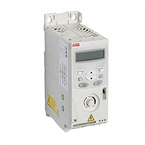
פיגורע 3.1: פראָנט view of the ABB ACS150 Micro Series AC VFD. This image shows the compact design of the drive, including the integrated control panel and cooling fins.

Figure 3.2: Key components of the ABB ACS150 VFD. This diagram highlights important features such as the removable clip for brand labeling, integrated interface, FlashDrop connection, integrated potentiometer, I/O connections, analog input signal selector (U/I), EMC filter grounding screw (EMC), and varistor grounding screw (VAR). It also points to the input, brake resistor, and motor connections.
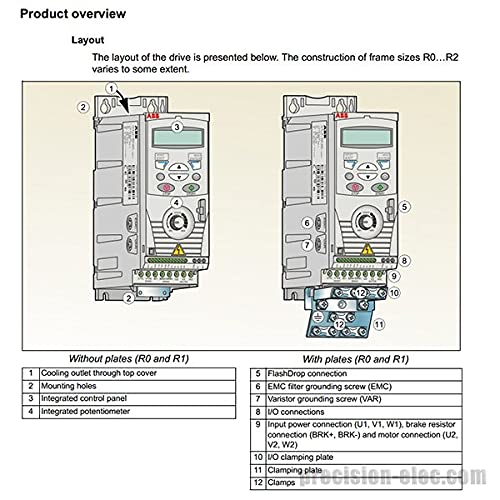
Figure 3.3: Layout of the drive for frame sizes R0 and R1. This image shows two configurations: one without plates and one with plates. Key numbered components include: 1) Cooling outlet through top cover, 2) Mounting holes, 3) Integrated control panel, 4) Integrated potentiometer, 5) FlashDrop connection, 6) EMC filter grounding screw (EMC), 7) Varistor grounding screw (VAR), 8) I/O connections, 9) Input power connection (U1, V1, W1), brake resistor connection (BRK+, BRK-) and motor connection (U2, V2, W2), 10) I/O clamping plate, 11) Clamping plate, and 12) Clamps.
4. טעכניש ספּעסאַפאַקיישאַנז
| באַשרייַבונג | ווערט |
|---|---|
| מאָדעל נומער | ACS150-03U-04A1-4 (P/N: 68582113) |
| מאַכט רייטינג | 2.0 הפּ |
| אַרייַנשרייַב וואָלtage | 480 VAC Three Phase |
| רעזולטאַט חלקtage | 480 וואַק |
| רעזולטאַט קראַנט | 4.1 Amps |
| אָפּצוימונג רייטינג | IP20 (NEMA 1/IP21 when wall mounted) |
| מאַונטינג טיפּ | וואנט בארג |
| פּראָדוקט דימענשאַנז (L x W x H) | 8 X 2.8 X 5.6 אינטשעס |
| פּונקט וואָג | 2.9 פונט |
| פאַבריקאַנט | FIG |
| ערשטער דאַטע בנימצא | 6 מערץ 2015 |
5. ייַנמאָנטירונג און סעטאַפּ
5.1 מאַונטינג
The ACS150 drive is designed for wall mounting. Ensure the mounting surface is stable and capable of supporting the drive's weight. Allow adequate clearance for ventilation around the drive, especially above the cooling outlet (refer to Figure 3.3, item 1).
5.2 עלעקטריקאַל קאַנעקשאַנז
All electrical connections must be performed by a qualified electrician in accordance with all applicable electrical codes. Ensure power is disconnected before making any connections.
5.2.1 מאַכט קאַנעקשאַנז
Connect the three-phase 480 VAC input power to terminals L1, L2, and L3. Connect the motor to terminals U2, V2, and W2. Ensure proper grounding of the drive and motor frame. Refer to the diagram below for an overview of power connections.

Figure 5.1: Power connections and control interfaces. This diagram illustrates the wiring for the 3-phase power supply (L1, L2, L3), input choke, EMC filter, brake chopper, brake resistor, and AC motor (U2, V2, W2). It also shows the control interface connections including programmable digital inputs (DI1-DI5), analog input (AI), relay output, and various grounding points.
5.2.2 Control Connections (I/O Terminals)
The drive features various I/O terminals for control signals. The default connection of control signals depends on the application macro selected. Refer to the diagram below for the I/O terminal layout.
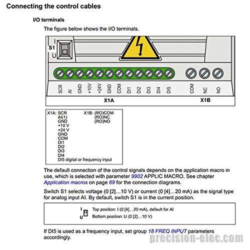
Figure 5.2: I/O terminals (X1A and X1B). This diagram details the pinout for analog input (AI), ground (GND), +10V, +24V, common (COM), and digital inputs (DI1-DI5) on X1A. X1B shows relay output connections (COM, NC, NO). It also indicates the S1 switch for selecting analog input signal type (current or voltagאון).
The S1 switch selects the voltage (0 [2]...10 V) or current (0 [4]...20 mA) as the signal type for analog input AI. By default, switch S1 is in the current position. If DI5 is used as a frequency input, set group 18 FREQ INPUT parameters accordingly.
6. אַפּערייטינג ינסטרוקטיאָנס
The ACS150 VFD can be operated via its integrated control panel or external control signals connected to the I/O terminals. The integrated control panel allows for setting parameters, monitoring drive status, and manual control.
6.1 קאָנטראָל פּאַנעל אָפּעראַציע
- אָנהייב / האַלטן: Use the dedicated buttons on the control panel to start and stop the motor.
- גיכקייַט קאָנטראָל: Adjust the integrated potentiometer (refer to Figure 3.2) to change the motor speed.
- פּאַראַמעטער באַשטעטיקן: Navigate through menus using the arrow keys and enter/exit buttons to adjust drive parameters such as acceleration/deceleration times, motor data, and I/O configurations.
- מאָניטאָרינג: The display shows real-time operational data like motor speed, current, voltage, and fault codes.
6.2 פונדרויסנדיק קאָנטראָל
The drive can be controlled remotely using digital inputs for start/stop commands, analog inputs for speed reference, and relay outputs for status indication. Refer to the wiring diagrams in Section 5.2 for proper connections and the drive's programming manual for parameter configuration.
7. וישאַלט
Regular maintenance ensures the longevity and reliable operation of the ACS150 VFD. Always disconnect power before performing any maintenance.
- רייניקונג: Periodically clean the cooling fins and fan to ensure proper airflow and prevent overheating. Use compressed air to remove dust and debris.
- פֿאַרבינדונגען: Check all electrical connections for tightness and signs of corrosion. Retighten if necessary.
- ענוויראָנמענטאַל קאָנטראָל: זיכער מאַכן אַז די אָפּערייטינג סביבה בלייבט אין די ספּעציפֿישע טעמפּעראַטור און הומידיטי לימאַץ.
- פען אויסטויש: The cooling fan has a limited lifespan. Replace it if it becomes noisy or stops functioning. Refer to the drive's service manual for fan replacement procedures.
8. טראָובלעשאָאָטינג
This section provides general troubleshooting tips for common issues. For detailed fault codes and remedies, refer to the comprehensive ABB ACS150 user manual.
| פּראָבלעם | מעגלעך סיבה | לייזונג |
|---|---|---|
| Drive does not power on | No input power; Blown fuse; Internal fault | Check power supply; Inspect fuses; Contact ABB support if internal fault suspected. |
| מאָטאָר טוט נישט לויפן | Incorrect wiring; Parameter settings; Fault trip | Verify motor and control wiring; Check drive parameters (e.g., start command, speed reference); Clear fault and investigate cause. |
| אָווערקוררענט שולד | Motor overload; Short circuit; Rapid acceleration | Reduce load; Check motor and cables for shorts; Increase acceleration time. |
| אָווערוואָלtagE שולד | הויך אַרייַנשרייַב וואָלtage; Rapid deceleration; Regenerative load | קוק אַרייַנשרייַב וואָלtage; Increase deceleration time; Consider adding a braking resistor if regenerative load is present. |
| אָוווערכיטינג שולד | Blocked ventilation; High ambient temperature; Fan failure | Clear obstructions; Ensure adequate cooling; Check and replace fan if necessary. |
9. וואָראַנטי און שטיצן
Specific warranty terms and conditions for the ABB ACS150-03U-04A1-4 are not provided within this manual. Please refer to the original purchase documentation or contact ABB customer support for detailed warranty information.
For technical support, service, or spare parts, please contact your local ABB representative or visit the official ABB website. Ensure you have the product model number (ACS150-03U-04A1-4) and serial number ready when contacting support.
ABB Official Webפּלאַץ: www.abb.com


