
1. הקדמה
This manual provides essential information for setting up and operating your AITRIP ESP32-S3-WROOM-1 N8R8 Development Board and its accompanying breakout boards. The ESP32-S3 is a powerful microcontroller unit (MCU) integrating 2.4GHz Wi-Fi and Bluetooth 5 (LE) capabilities, designed for Internet of Things (IoT) applications. This kit includes expansion boards to facilitate easy prototyping and permanent installations.

בילד 1.1: איבערview of the AITRIP ESP32-S3-WROOM-1 N8R8 Development Board and Breakout Boards.
2. וואָס איז אין דער קעסטל
דיין פּעקל זאָל אַנטהאַלטן די פאלגענדע זאכן:
- 2 x ESP32-S3-WROOM-1 N8R8 Development Boards
- 2 x Breakout Board Shield Terminal Adapters
Video 2.1: An unboxing of a similar ESP32-S3 kit, demonstrating typical package contents and initial handling.
3. פֿעיִקייטן
- ESP32-S3-WROOM-1 N8R8 Module: Integrated 2.4GHz Wi-Fi (802.11 b/g/n) and Bluetooth 5 (LE) for robust wireless communication.
- Dual-Core Processor: Equipped with an LX7 dual-core processor, operating at up to 240MHz.
- זכּרון: Built-in 512 KB SRAM (TCM), 8MB Flash, and 2MB PSRAM for ample program and data storage.
- GPIO Expansion: 36 programmable GPIO pins and rich communication interfaces. The breakout boards expand 1 GPIO pin to 2, allowing for extensive pin reuse.
- וסב קאַנעקטיוויטי: Features both USB-to-UART Port and ESP32-S3 USB Port for flexible power supply and programming options.
- Long Range Communications: Supports Bluetooth Mesh and Coded PHY for extended communication range.
- High-Speed Octal SPI: Supports larger capacity high-speed Octal SPI Flash and off-chip RAM.

Image 3.1: Block diagram illustrating the ESP32-S3 module's internal components and connectivity.
4. סעטאַפּ אינסטרוקציעס
To begin using your ESP32-S3 Development Board with the breakout adapter, follow these steps:
- ידענטיפיצירן קאַמפּאָונאַנץ: Locate the ESP32-S3-WROOM-1 N8R8 Development Board and one of the breakout board adapters.
- אויסגלייַכן שפּילקעס: Carefully align the pins of the ESP32-S3 Development Board with the corresponding female headers on the breakout board. Ensure correct orientation to prevent damage.
- Insert Board: Gently press the ESP32-S3 board into the breakout board until it is securely seated. Avoid excessive force.
- פאַרבינדן פּעריפעראַלס: Once assembled, you can connect your sensors, actuators, and other components to the expanded GPIO pins on the breakout board.

Image 4.1: The ESP32-S3 Development Board correctly installed onto a breakout board.

בילד 4.2: דעטאַלירט view of the breakout board, showing front and back.
Video 4.3: Demonstration of installing an ESP32 board onto a screw terminal breakout board.
5. אַפּערייטינג ינסטרוקטיאָנס
The ESP32-S3 Development Board is designed for versatility in IoT projects. Here are key aspects of its operation:
5.1. Pinout and GPIO Usage
The breakout boards provide easy access to all GPIO pins. Refer to the pinout diagram for specific pin functions. Each GPIO pin can be configured as input or output, supporting various digital and analog functionalities.
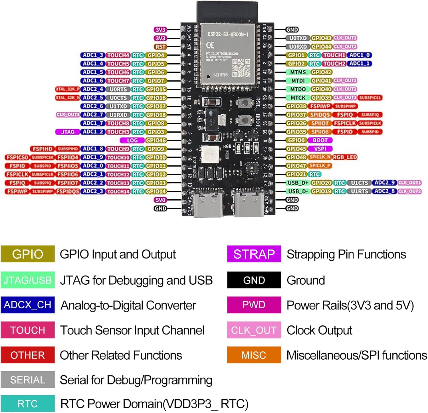
Image 5.1: Detailed pinout diagram for the ESP32-S3-WROOM-1 N8R8 module, indicating GPIO functions.
5.2. מאַכט צושטעלן
The board can be powered via the USB-to-UART port or the ESP32-S3 USB port. Ensure your power source provides stable 5V DC. The breakout boards may offer additional power input options, such as a DC barrel jack for 7-12V input, which can power both the breakout board and the core board simultaneously.
5.3. פּראָגראַממינג
The ESP32-S3 can be programmed using various development environments, including the Arduino IDE or Espressif's ESP-IDF. Connect the board to your computer via a USB cable. The integrated USB-to-UART bridge facilitates code upload and serial communication.
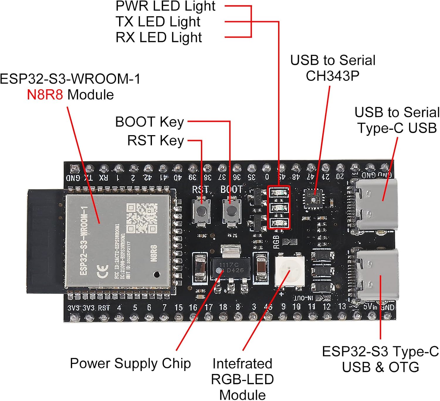
Image 5.2: Close-up of the ESP32-S3 module, highlighting USB ports, buttons, and power supply chip.
ווידעא 5.3: איבערview of a Meshnology ESP32 Breakout Board, demonstrating its features and compatibility.
6. ספּעסאַפאַקיישאַנז
| שטריך | באַשרייַבונג |
|---|---|
| מאָדעל נאָמען | ESP32 S3 Development Board |
| פּראַסעסער | LX7 Dual-Core (up to 240MHz) |
| באַראַן | 512 KB SRAM (TCM), 2MB PSRAM |
| פלאַש זכּרון | 8 מב |
| ווירעלעסס קאַנעקטיוויטי | 2.4GHz Wi-Fi (802.11 b/g/n), Bluetooth 5 (LE) |
| GPIO פּינס | 36 פּראָוגראַמאַבאַל GPIOs |
| אָפּערייטינג סיסטעם | FreeRTOS |
| Power Input (USB) | 5V DC (דורך USB-C) |
| Power Input (Breakout) | 7-12V DC (via DC barrel jack, if available on breakout) |
| פּונקט וואָג | 0.2 ounces (approx. per board) |
| פּעקל דימענשאַנז | 2.1 x 1.2 x 0.2 inches (approx. per board) |

Image 6.1: Dimensions of the ESP32-S3 Development Board and the breakout adapter.
7. וישאַלט
To ensure the longevity and optimal performance of your ESP32-S3 Development Board and breakout boards, consider the following maintenance tips:
- שעפּן מיט זאָרג: Avoid dropping the boards or subjecting them to physical shock.
- האַלטן טרוקן: Protect the boards from moisture and humidity. Store them in a dry environment.
- ריינקייַט: Keep the boards free from dust and debris. Use a soft, dry brush or compressed air for cleaning.
- סטאַטיק שוץ: Always handle the boards with anti-static precautions to prevent damage from electrostatic discharge.
- מאַכט אַוועק: Disconnect power before making any changes to wiring or components.
8. טראָובלעשאָאָטינג
If you encounter issues with your ESP32-S3 Development Board, consider these common troubleshooting steps:
- מאַכט ישוז: Ensure the board is receiving adequate and stable power (5V via USB or 7-12V via external power supply on breakout). Check USB cable connections.
- קאַנעקטיוויטי פּראָבלעמס: Verify Wi-Fi and Bluetooth configurations in your code. Ensure correct antenna connection if applicable.
- פּראָגראַמירן טעותים: Double-check your code for syntax errors and correct pin assignments. Ensure the correct board and port are selected in your IDE.
- GPIO Malfunction: Confirm that GPIO pins are correctly configured as input/output and that external components are wired correctly.
- ברעט נישט דעטעקטירט: Reinstall USB drivers if the board is not recognized by your computer. Try a different USB port or cable.
- באַשטעטיק קנעפּל: Use the onboard Reset button to restart the module if it becomes unresponsive.
9. וואָראַנטי און שטיצן
פֿאַר וואָראַנטי אינפֿאָרמאַציע און טעכנישע שטיצע, ביטע זען די פאַבריקאַנט'ס באַאַמטער webזייטל אדער קאנטאקט זייער קאסטומער סערוויס גלייך. האלט אייער קויף קוויטל אלס באווייז פון קויפן.